Modern garage installations require sophisticated electrical distribution systems that comply with stringent safety regulations while accommodating diverse power requirements. A properly designed garage consumer unit serves as the heart of the electrical infrastructure, managing circuits for lighting, power tools, electric vehicle charging, and workshop equipment. Understanding the fundamental wiring diagram principles and regulatory requirements ensures both compliance with current standards and optimal performance for years to come.
The complexity of contemporary garage electrical systems has evolved significantly, driven by increasing power demands and enhanced safety protocols. From basic lighting circuits to high-capacity EV charging points, today’s garage consumer units must handle varied loads while maintaining robust protection mechanisms. This technical evolution reflects broader changes in how garages function within modern properties, transitioning from simple storage spaces to multi-purpose workshops and charging stations.
Understanding UK domestic consumer unit regulations for garage installations
Compliance with UK electrical regulations forms the cornerstone of safe garage consumer unit installation. The regulatory framework encompasses multiple standards that work together to ensure electrical safety, proper installation methods, and long-term reliability. These regulations have evolved to address modern electrical challenges while maintaining backward compatibility with existing installations.
BS 7671 IET wiring regulations requirements for outbuilding electrical systems
BS 7671 establishes the fundamental requirements for garage consumer unit installations, particularly focusing on outbuilding electrical systems. The regulations mandate specific installation methods, cable routing requirements, and protection device specifications that differ from main dwelling installations. Circuit designers must consider the unique environmental conditions present in garage environments, including temperature variations, humidity levels, and potential exposure to mechanical damage.
The regulations specify minimum clearances around consumer units, accessibility requirements for maintenance, and proper labelling protocols. Particular attention must be paid to the selection of appropriate IP ratings for components exposed to garage environments. The standards also address the coordination between main dwelling installations and garage submains, ensuring proper discrimination and safety isolation capabilities.
Part P building regulations compliance for detached garage consumer units
Part P Building Regulations introduce additional compliance requirements for garage consumer units, particularly when installed in detached structures. These regulations mandate notification procedures for electrical work, competent person schemes, and inspection requirements that extend beyond basic BS 7671 compliance. The regulations recognise the increased complexity of garage electrical systems and the potential for higher risk installations.
Detached garage installations often require enhanced earthing arrangements and may need separate earth electrodes depending on the supply arrangement. The regulations specify minimum conductor sizes for submain cables and establish requirements for protective device coordination between the main dwelling and garage installations. Compliance certificates and electrical installation certificates become mandatory for most garage consumer unit installations, creating a comprehensive documentation trail for future reference.
RCD protection standards under amendment 3 for garage circuits
Amendment 3 to BS 7671 introduced enhanced RCD protection requirements that significantly impact garage consumer unit design. The standards now mandate RCD protection for most garage circuits, with specific requirements for socket outlet circuits and lighting installations. Type A RCDs have become the minimum standard for installations containing electronic equipment, while Type AC devices remain acceptable for purely resistive loads.
The enhanced protection requirements address the increased prevalence of electronic equipment in garage environments, including variable speed drives, electronic battery chargers, and modern power tools.
RCD protection must be provided for all socket outlet circuits rated up to 32A, with specific discrimination requirements for installations containing multiple RCD devices.
The regulations also address the use of RCBO devices as an alternative to traditional MCB/RCD combinations, offering improved selectivity and reduced nuisance tripping.
IP rating classifications for consumer units in Non-Heated outbuildings
Environmental protection requirements for garage consumer units differ significantly from internal domestic installations due to the challenging conditions typically present in outbuilding environments. The IP rating system provides a standardised method for specifying protection levels against solid particles and liquid ingress. Garage installations typically require enhanced protection levels to ensure reliable long-term operation.
IP54 represents the minimum acceptable protection level for most garage consumer units, providing protection against dust ingress and splashing water from any direction. Higher protection levels may be necessary in particularly challenging environments or where the consumer unit location exposes it to direct water ingress. The selection of appropriate IP ratings must consider both
IP54 represents the minimum acceptable protection level for most garage consumer units, providing protection against dust ingress and splashing water from any direction. Higher protection levels may be necessary in particularly challenging environments or where the consumer unit location exposes it to direct water ingress. The selection of appropriate IP ratings must consider both mechanical protection and condensation risk, especially in unheated outbuildings where temperature swings can be extreme. In practice, many designers now favour IP65 metal enclosures for garages with frequent wash‑down, vehicle valeting, or pressure washing activity. Whatever the chosen rating, cable glands, blanks, and knockouts must be installed to the same IP standard as the consumer unit itself to maintain the declared level of protection.
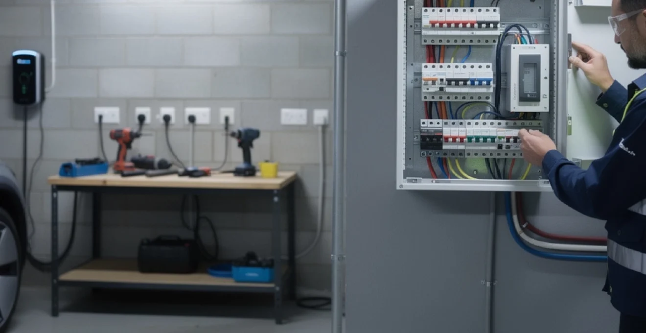
Essential components and circuit protection devices for garage consumer units
A basic wiring diagram for a garage consumer unit revolves around a few critical components: the main switch or isolator, RCDs or RCBOs, MCBs, surge protection devices, and the neutral and earth bars. Each element plays a distinct role in how energy is distributed and how faults are managed. When you translate that diagram into a physical installation, the key decisions concern device ratings, type selection, and how you group circuits to balance safety, selectivity, and usability.
Garage consumer units are often tasked with feeding mixed loads: small power tools, fixed machinery, EV chargers, outdoor sockets, and lighting circuits. This makes protection device coordination more important than in a simple domestic board. Well‑designed protection hierarchies ensure that only the faulty circuit disconnects, rather than plunging the whole garage into darkness if one tool develops a fault. In the following subsections, we look at how to choose appropriate MCBs, RCD types, SPDs, and busbar arrangements for a typical modern garage.
MCB selection criteria for workshop power tools and electric vehicle charging
Miniature circuit breakers (MCBs) are the primary overcurrent protection devices in a garage consumer unit wiring diagram. Their rating and tripping characteristics must be selected to match both the cable size and the load type connected to each circuit. For general-purpose socket outlets, 20A or 32A MCBs are common, while fixed workshop equipment and EV chargers may each require a dedicated radial circuit with its own breaker. The overarching rule remains simple: the MCB must protect the cable, not the appliance.
MCBs are classified by tripping curve (typically Type B, C, or D) which defines how they respond to inrush currents. Type B MCBs are normally suitable for standard domestic and light commercial circuits, including most portable power tools. However, heavy workshop machinery with high inrush currents, such as large induction motors or compressors, may justify Type C devices to avoid nuisance tripping. For an EV charging point, manufacturers usually specify a dedicated circuit, often 32A on 6 mm² cable, protected by a Type B MCB or RCBO in accordance with their installation instructions.
When sizing MCBs for garage installations, you should consider not only the steady‑state load but also diversity and realistic usage patterns. Will multiple high‑load tools ever run together on the same circuit? If so, a radial design with a 20A or 32A breaker may be more appropriate than a smaller 16A circuit.
MCB selection must always be coordinated with voltage drop limits, cable installation method, and the maximum permissible earth fault loop impedance given in BS 7671.
A careful design process avoids under‑sizing that triggers nuisance tripping, or over‑sizing that could leave the cable inadequately protected under fault conditions.
Type A and type AC RCD configuration for mixed loading applications
Residual current devices sit alongside MCBs in the garage consumer unit layout, providing life‑saving protection against electric shock and some types of fire. With the proliferation of electronic loads in garages—battery chargers, variable speed drives, welders, and EV chargers—the choice between Type AC and Type A RCDs has become critical. Type AC RCDs detect only pure AC residual currents, whereas Type A devices additionally detect pulsating DC components, which are increasingly common with modern electronics.
For this reason, most contemporary designs treat Type A RCDs as the default choice for garage consumer units, particularly where any form of electronic power conversion is present. BS 7671 now strongly discourages the use of Type AC RCDs for circuits supplying equipment likely to produce DC residual currents. In mixed‑load garages, a typical configuration might employ one or more 30 mA Type A RCDs as front‑end devices, or individual Type A RCBOs on each outgoing circuit, to avoid shared RCD tripping and maintain discrimination.
From a wiring diagram perspective, you must decide whether to adopt a split‑load arrangement (one RCD feeding several MCBs) or an all‑RCBO layout. An all‑RCBO board is usually the most robust option for garages with critical circuits such as freezers or EV chargers, because a single RCD trip does not remove power from unrelated circuits. Have you ever had an RCD trip and lost lighting and sockets together? Using RCBOs is the equivalent of giving each circuit its own “bodyguard,” improving both safety and usability.
SPD installation requirements under BS EN 61643-11 for garage circuits
Surge protection devices (SPDs) are increasingly specified in consumer units, including those serving detached garages, in line with BS 7671 and BS EN 61643‑11. Their role is to protect sensitive equipment from transient overvoltages caused by lightning or switching events on the distribution network. Although a garage might seem less critical than the main dwelling, many now contain EV chargers, electronic inverters, CNC tools, and IT equipment that are highly sensitive to surges.
BS EN 61643‑11 classifies SPDs into Type 1, Type 2, and Type 3 devices. For a typical domestic installation where the main house already includes a Type 2 SPD, a submain‑fed garage board usually needs coordination rather than duplication. If the submain is long or exposed, a Type 2 SPD in the garage consumer unit may still be warranted to clamp residual surges as close as possible to the final circuits. In high‑risk areas or where the supply is via overhead lines, a risk assessment under BS 7671 Section 443 should be carried out to determine whether surge protection is required.
In a wiring diagram, the SPD is typically shown connected in parallel across the incoming phase and neutral, with a short, low‑impedance earth connection to the main earth bar. The phrase “as short as possible” is not just advice; longer leads significantly reduce SPD effectiveness. Think of an SPD as a lightning‑fast pressure relief valve: the shorter the pipe, the quicker it can release pressure. When you lay out the physical board, place the SPD close to the main switch or main RCD and keep conductor lengths within the manufacturer’s limits, generally less than 0.5 m from line and neutral to earth.
Neutral bar and earth bar sizing for submain distribution
The neutral and earth bars in a garage consumer unit are more than simple connection strips; they are integral parts of the fault protection and earthing system. Their current‑carrying capacity, number of terminals, and segregation must all suit the submain design and the number of outgoing circuits. For TN‑S and TN‑C‑S systems, the garage neutral bar must comfortably carry the maximum expected load current, while the earth bar must be rated for prospective fault currents long enough for protective devices to operate.
In many compact “garage units,” manufacturers provide a single neutral bar and earth bar sized to match the maximum rating of the enclosure, such as 40A or 63A. However, if you are feeding a more substantial workshop or EV‑ready garage with a 63A or 80A submain, it is important to check the manufacturer’s datasheet for busbar and terminal ratings. Overloading the neutral bar or using undersized earth terminals can create hidden weak points that may only reveal themselves during a serious fault. Designers should also provide spare ways on both bars to allow for future circuit additions without improvised terminations.
Where multiple RCDs or RCBOs are used, correct segregation of neutrals is essential. Each RCD‑protected group requires its own dedicated neutral bar, and circuits must not share neutrals across different RCDs. In wiring diagrams, this is often shown as separate neutral bars linked only on the line side of the RCDs. Failing to respect this segregation can lead to puzzling nuisance tripping and measurement anomalies during testing. The earth bar, by contrast, is typically common to all circuits within the consumer unit but must be properly labelled and bonded to the installation’s main earthing terminal.
Cable sizing and installation methods for garage submain circuits
The submain cable that feeds a garage consumer unit from the main dwelling is the backbone of the entire outbuilding installation. Cable sizing must account for design current, protective device rating, installation method, ambient temperature, grouping, and voltage drop over the route. For many domestic garages, submains are commonly protected at 40A–63A and installed as 3‑core steel wire armoured (SWA) cable, particularly when run externally or underground.
In practice, a 6 mm² or 10 mm² SWA submain is typical, but the correct size should always be determined using BS 7671 Appendix 4 calculations. You need to consider not just the maximum demand of the garage (lighting, sockets, EV charging, and workshop loads), but also the length of the run and how the cable is installed. For example, a long buried run to a detached garage at the end of a garden may require a larger cross‑section to keep voltage drop within the recommended 3% for lighting and 5% overall guideline often applied in domestic design.
Installation methods vary: cables may be clipped direct to a masonry wall, buried in ducting, or run in PVC conduit or trunking inside the property. Each method has a different correction factor for current‑carrying capacity. Have you ever noticed how a cable tucked tightly in insulation runs hotter than one clipped openly to a wall? That is exactly why BS 7671 insists on applying installation correction factors when sizing submains. For garage feeds, avoiding prolonged runs embedded in thermal insulation wherever possible is good practice, both to improve current capacity and to simplify future inspection.
Mechanical protection is also a major consideration. When a cable passes through a garden, driveway, or workshop area, it must be adequately protected from impact and accidental damage. SWA cable with appropriate gland kits offers both mechanical protection and a means to provide a robust earth connection via the armour. Where PVC twin‑and‑earth is used inside the dwelling, transition to SWA is made at a suitable enclosure with proper earthing and shrouded glands. All of these details should be reflected on your wiring diagram so that installers and inspectors can see, at a glance, how the submain route is constructed.
Circuit design layout for typical garage electrical requirements
Once the submain and consumer unit specification are defined, attention turns to the internal circuit layout within the garage. A clear wiring diagram helps you visualise how power flows from the incoming submain through the main switch, RCDs or RCBOs, and into each final circuit. Typical garage installations include a socket circuit for general use, one or more dedicated radials for heavy workshop equipment, a lighting circuit, and often a dedicated EV charging circuit.
Each circuit type has its own design rules and recommended protective device ratings. Balancing these circuits across the available RCDs or RCBOs reduces the likelihood that a single fault will disable critical loads such as lighting or freezers. It is often helpful to think of the garage as a small, self‑contained distribution network: by drawing the wiring diagram with zones—lighting, general sockets, fixed equipment, and EV charging—you can quickly see where dedicated protection or larger cable sizes are justified.
32A ring final circuit configuration for general socket outlets
Although many modern designers favour radial circuits, the 32A ring final circuit remains common in UK domestic settings and can be suitable for larger garages that require flexibility and a high density of socket outlets. A ring final circuit uses 2.5 mm² twin‑and‑earth cable looped from the MCB at the consumer unit, around all sockets, and back to the same MCB, effectively providing two parallel paths for current. This configuration allows a 32A MCB to protect cables that would otherwise be limited to 20A in a radial arrangement.
In the context of a garage consumer unit wiring diagram, the ring final circuit is represented as a closed loop from the 32A MCB, via all socket outlets, returning to the same breaker. BS 7671 lays down strict requirements for continuity testing and maximum floor area, and care must be taken to ensure all connections are properly terminated. Ring circuits are particularly useful in larger workshops where sockets are distributed around all walls, providing balanced load sharing and redundancy if one leg is slightly compromised.
However, designers must be mindful of potential pitfalls. If alterations are made in future and the ring is broken, the circuit may unintentionally become a 2.5 mm² radial still protected at 32A—an unsafe condition. For that reason, clear circuit labelling and good documentation are crucial. Some electricians prefer to design garages solely with radial circuits for simplicity and future modification safety. If you choose a ring final for your garage, ensure that it is thoroughly tested (end‑to‑end and cross‑loop continuity, polarity, and R1+R2 measurements) and that any future changes are carried out by competent persons who understand ring principles.
16A radial circuit design for high-power workshop equipment
Many garages double as workshops housing fixed equipment such as pillar drills, table saws, air compressors, or welders. These loads often benefit from dedicated radial circuits, typically protected at 16A or 20A, to avoid interference with general socket outlets and to provide clearer fault isolation. A 16A radial circuit is usually wired in 2.5 mm² twin‑and‑earth cable (for typical installation methods) from its own MCB or RCBO in the garage consumer unit to a single or small group of outlets serving the equipment.
From a design perspective, assigning specific tools their own radial reduces voltage dips and nuisance tripping on the general socket circuit when motor loads start. It also simplifies load calculations: you can design the radial purely around the requirements of the equipment, applying manufacturer data for starting currents and duty cycles. In your wiring diagram, these radials should be clearly marked as “dedicated” or “workshop radial,” and where industrial‑style connectors (such as BS 4343/IEC 60309 blue 16A sockets) are used, their locations should be indicated.
The choice between 16A and 20A protection often comes down to anticipated load and cable run length. For heavier or future‑proofed equipment, a 20A radial with 2.5 mm² or even 4 mm² cable may be appropriate, especially if runs are long or installed in insulation. A useful analogy is designing a separate spur of plumbing for a power shower: by giving it its own supply, you stop it stealing pressure from the rest of the house. In the same way, a dedicated 16A or 20A radial stops a large saw or compressor from “robbing” current from your general‑use sockets.
6A lighting circuit layout with emergency lighting integration
Lighting circuits in garages are typically protected by a 6A MCB or RCBO, using 1.0 mm² or 1.5 mm² twin‑and‑earth cable depending on design preference and circuit length. A well‑thought‑out lighting layout improves both safety and usability, especially in garages used for precision work or vehicle maintenance. The wiring diagram will normally show a feed from the 6A protective device to one or more switch locations, then on to ceiling luminaires, external security lights, or task lighting over benches.
Integration of emergency lighting is particularly important in larger or more complex garages, or where the space is used commercially. Even in domestic settings, a single self‑contained emergency bulkhead or maintained LED fitting can provide invaluable illumination if the main RCD or MCB trips while the garage is occupied. Emergency luminaires are usually supplied from the same final circuit as the normal lighting, ensuring they sense a loss of power correctly. Their presence should be noted on the circuit schedule and wiring diagram, with test switches or key switches included where required by standards.
Switching arrangements can range from simple one‑way switches by the personnel door to two‑way switching from the house and the garage, or occupancy sensors for automatic control. When designing the lighting circuit, think about how you will use the space at night: do you need separate switching for outside security lighting, or dimmable task lighting zones? These decisions affect the number of conductors in switch drops and junction boxes, which should be clearly indicated on your diagram to avoid confusion during installation and future changes.
Dedicated EV charging point circuit using 32A type 2 installation
As electric vehicles become more common, dedicated EV charging circuits are now a frequent feature of garage consumer unit layouts. A typical domestic EV charger rated at 7.2 kW operates at 32A on a single‑phase supply and requires its own radial circuit in accordance with manufacturer instructions and BS 7671 Section 722. This circuit is usually wired in 6 mm² cable (or larger, depending on run length and installation method) and protected by a suitably rated MCB or RCBO, often combined with additional RCD or RDC‑DD protection specific to EV charging requirements.
In the wiring diagram, the EV circuit is shown as a dedicated radial from the garage consumer unit to the charger location, with clear indication of protective devices and any load management equipment. Many modern EV charge points integrate their own DC fault detection, allowing the use of a Type A RCD upstream, while others may demand a Type B RCD. Always verify the charger manufacturer’s documentation and BS 7671 requirements before finalising the design. Given the sustained high load, diversity should not be applied lightly to EV circuits; they are typically treated as continuous full‑load circuits in maximum demand calculations.
Because EV charging can significantly increase the total load on a domestic supply, designers must also consider supply capacity and main service head limits. Where necessary, load curtailment or smart chargers that modulate output based on available capacity can be included. Conceptually, you can imagine the EV charger as a “second cooker” permanently wired into the garage: it needs its own robust, well‑protected path from the consumer unit, with no sharing or spurs to other loads. Careful labelling and separate isolation near the charger ensure safe maintenance and clear identification for users.
Earthing and bonding arrangements for TN-S and TN-C-S supply systems
Earthing and bonding arrangements are foundational to safe operation of any garage consumer unit, and the approach varies depending on whether the supply is TN‑S, TN‑C‑S (PME), or TT. For TN‑S and TN‑C‑S systems, the garage is normally supplied via a submain from the dwelling’s main consumer unit, sharing the same main earthing terminal. The wiring diagram should clearly indicate the earthing system type and how the garage earth bar connects back to the origin.
On TN‑S systems, the earthing conductor from the supply is separate from the neutral and typically derived from the metallic sheath of the supply cable. For TN‑C‑S systems, the PEN conductor from the network is split into separate neutral and earth at the service head. In both cases, the submain to the garage will include a circuit protective conductor (CPC), either as a core within the cable or via SWA armour, sized in line with BS 7671 requirements. Additional bonding within the garage may be required, particularly where extraneous‑conductive‑parts, such as metal water pipes, structural steel, or inspection pits, are present.
Special care is needed where EV charging is installed on TN‑C‑S systems, because of the risk associated with a broken PEN conductor. BS 7671 Section 722 outlines several permitted methods to mitigate this risk, including devices that detect PEN faults and disconnect the supply, or adopting a TT earthing arrangement for the EV circuit. In some designs, the entire garage may be treated as a TT island with its own earth electrode and RCD protection, while the dwelling remains TN‑C‑S. Your wiring diagram should document whichever strategy is used, including the location of any earth rods, links, and separation points.
Finally, main protective bonding conductors, which connect the earthing system to incoming metallic services (such as gas and water), must be correctly sized and located. For detached garages with their own incoming services, bonding may be required both at the dwelling and at the outbuilding, depending on how services are routed. Think of earthing and bonding as the “safety net” under your entire electrical system: invisible most of the time, but vital when something goes wrong. Clear schematic representation of these conductors in your garage consumer unit wiring diagram greatly assists future inspection, testing, and fault‑finding.
Testing and certification procedures for garage consumer unit installations
No garage consumer unit installation is complete until it has been fully tested and documented in accordance with BS 7671. Testing verifies that the wiring diagram you designed has been translated into a safe, functioning system on site. For new circuits and consumer units, this includes continuity of protective conductors, insulation resistance, polarity checks, earth fault loop impedance measurements, RCD/RCBO trip time tests, and functional testing of all devices and controls.
In the UK domestic context, work involving a new consumer unit or new circuits to an outbuilding typically requires an Electrical Installation Certificate (EIC) supported by detailed test results. Where work falls under the scope of Part P Building Regulations, either the installer must be registered with a competent person scheme and notify the work, or Local Authority Building Control must be engaged. Proper certification is not just a legal formality; it provides a baseline record for future inspections and proves that the installation met the standards in force at the time of completion.
From a practical standpoint, many electricians follow a systematic test sequence starting at the garage consumer unit and working outwards to each circuit. For example, you might begin with dead tests (continuity and insulation resistance), then progress to live tests (loop impedance and RCD performance) once it is safe to energise the system. Have you ever tried to fault‑find in an installation with no previous test records? It is a little like trying to navigate a city without a map. By completing and retaining accurate schedules of test results and circuit details, you make life far easier for anyone who works on the installation in the future.
Periodic inspection and testing are equally important, especially in garages exposed to harsh conditions, mechanical damage, or frequent adaptations. Although the recommended interval varies depending on usage and risk, many domestic outbuildings benefit from inspection every 5–10 years, or upon change of ownership. During these inspections, the original wiring diagram and certificates should be referenced to identify any modifications or departures from the original design. In this way, good documentation and rigorous testing procedures close the loop between design, installation, and long‑term safe operation of garage consumer units.