Few automotive frustrations rival the experience of collecting your vehicle from an alignment service, only to discover that your steering wheel remains stubbornly off-centre as you navigate home. This persistent misalignment represents more than a minor aesthetic annoyance—it signals underlying issues with either the alignment procedure itself or deeper mechanical problems within your vehicle’s steering and suspension systems. Understanding why this occurs and how to rectify it requires knowledge of precise alignment principles, diagnostic methodologies, and the interconnected geometry of modern steering systems. When your steering wheel refuses to centre despite professional alignment work, you’re facing a situation that demands methodical investigation and expert correction to restore both driving comfort and vehicle safety.
The relationship between wheel alignment angles and steering wheel position involves remarkably tight tolerances. Modern alignment specifications typically allow deviations measured in fractions of a degree, yet even these minimal variations can translate into noticeable steering wheel offset. Professional technicians must account for numerous variables simultaneously—including individual toe settings, thrust angle relationships, steering rack centralisation, and the mechanical condition of steering components—to achieve the centred steering wheel position drivers rightfully expect after alignment services.
Identifying steering wheel Off-Centre conditions after Four-Wheel alignment
Recognition of steering wheel misalignment begins with careful observation during normal driving conditions. The diagnostic process requires distinguishing between various manifestations of steering irregularities, as each points toward specific underlying causes. Accurate identification forms the foundation for effective correction, preventing unnecessary adjustments that might compound rather than resolve the issue.
Measuring steering wheel spoke position using the clock method
The clock face method provides a standardised approach for quantifying steering wheel offset. When your vehicle travels straight on level ground with minimal steering input, observe the steering wheel’s spoke position relative to a perfectly horizontal orientation. Technicians often describe deviation using clock positions—for example, “the wheel sits at ten past one” indicates the top spoke points slightly right of vertical. Precise measurement matters significantly; deviations exceeding fifteen degrees (approximately half an hour on the clock face) typically indicate substantial alignment errors requiring immediate correction. Lesser deviations between five and fifteen degrees may stem from subtler causes including asymmetric tie rod adjustments or minor thrust angle offsets. Document the deviation direction and magnitude before beginning diagnostic procedures, as this baseline measurement proves invaluable when verifying correction effectiveness.
Differentiating between toe misalignment and steering rack centralisation issues
Two distinct mechanical conditions produce visually similar steering wheel offset, yet require fundamentally different correction approaches. Toe misalignment occurs when the alignment technician achieves correct total toe specifications whilst distributing the adjustment unevenly between left and right wheels. The steering rack remains properly centralised, but unequal individual toe settings create the offset. Conversely, steering rack centralisation problems arise when the rack itself sits off-centre within its housing, even though individual toe measurements may appear balanced. Distinguishing between these conditions requires examining individual wheel toe readings rather than simply total toe values. When left and right toe measurements differ by more than 0.05 degrees whilst total toe remains within specification, you’re observing asymmetric toe distribution. If individual toe readings appear nearly identical yet the steering wheel remains off-centre, suspect rack centralisation issues or problems within the steering column itself.
Detecting asymmetric tie rod length discrepancies
Visual inspection of tie rod lengths provides immediate insight into alignment quality. Park the vehicle on level ground and examine both tie rods from underneath, comparing the exposed thread length on each side’s adjustment sleeve. Significant visible differences—typically anything exceeding half an inch—suggest that one tie rod received disproportionate adjustment during the alignment procedure. This asymmetry often results from technicians chasing toe specifications without maintaining equal adjustment distribution. Professional alignment protocols demand that technicians make equal and opposite adjustments to left and right tie rods, preserving steering rack centralisation whilst achieving target toe angles. Asymmetric tie rod lengths virtually guarantee steering wheel offset, as the steering rack has been pulled off-centre to one side. Measuring exposed thread with precision callipers provides quantifiable data; differences exceeding 3mm warrant correction through the equal-length adjustment method.
Understanding thrust angle deviation and its effect on steering position
<p
Thrust angle describes the direction in which the rear axle effectively “pushes” the vehicle relative to its geometric centreline. When this thrust line deviates from zero, the vehicle naturally tracks slightly left or right, compelling you to hold the steering wheel off-centre simply to travel straight. In essence, the car behaves like a supermarket trolley whose rear wheels are skewed—you must steer against the deviation at all times. Even when front toe readings appear correct, an unchecked thrust angle error will force the steering wheel into a rotated position to compensate. Recognising this relationship is critical: if the vehicle drives straight with the steering wheel intentionally held off-centre, you are likely dealing with a thrust angle deviation rather than purely a front toe problem.
Root causes of Post-Alignment steering wheel misalignment
Once you’ve identified that the steering wheel is not straight after alignment, the next step is to uncover why. Many root causes originate not from catastrophic component failure, but from shortcuts or oversights during the alignment procedure itself. Others stem from worn steering parts that physically prevent accurate adjustment, even when alignment equipment reports that all values are within range. Understanding these specific causes helps you ask the right questions at the workshop and ensures technicians follow a methodical process rather than simply “tweaking” the toe to make the numbers turn green.
Improper steering wheel lock-to-lock centre point reference during alignment
Correct steering wheel centralisation begins before a single toe adjustment is made, with accurate identification of the steering rack’s true centre position. Technicians must rotate the steering from lock to lock, count the turns, and then position the wheel precisely at the midpoint before locking it in place with a steering wheel clamp. If this step is rushed or skipped, the alignment will be based on an incorrect reference, guaranteeing that the steering wheel will sit off-centre even if all suspension angles appear within spec. On vehicles with electric power steering or steering angle sensors, failing to use the correct centre point can also create conflicts with the electronic control unit, which assumes a different “straight ahead” position than the mechanical setup.
Unequal toe adjustment distribution between left and right tie rods
Many instances of a steering wheel not straight after alignment trace back to how the technician distributed toe adjustments between the two front wheels. While total toe may match the manufacturer’s specification, excessive correction applied to only one tie rod shifts the rack relative to the steering wheel, pulling the wheel off-centre. The correct approach involves making equal and opposite adjustments on each side whenever possible—for example, adding 0.10 degrees of toe-in on the left while removing 0.10 degrees on the right to maintain rack centralisation. When you see dramatically different exposed thread lengths on tie rods following an alignment, it’s a strong indicator that unequal toe adjustment distribution is the culprit.
Rear axle thrust line offset creating compensatory steering input
A rear axle that is not square to the chassis will generate a thrust angle that points slightly left or right, forcing you to hold the steering wheel at an angle to keep the vehicle tracking straight. This scenario is common on cars with solid rear axles that have suffered curb or pothole impacts, or on vehicles with adjustable rear suspension where camber or toe has not been set symmetrically. Even a thrust angle deviation as small as 0.20 degrees can be enough for a sensitive driver to notice a steering wheel misalignment. Modern four-wheel alignment procedures are designed to reference front toe settings to the rear thrust line, but if the operator ignores or fails to correct rear discrepancies, compensatory steering wheel offset becomes inevitable.
Worn or seized tie rod ends preventing accurate toe settings
Accurate front toe adjustment depends on free-moving, structurally sound tie rod ends and adjustment sleeves. When these components become seized by corrosion or their internal joints develop excessive play, alignment changes may not transfer predictably to the wheels. A technician may believe the toe has been set correctly based on static readings, yet the steering wheel can shift off-centre once the vehicle is driven and the worn joints settle under load. In severe cases, attempting to rotate a seized adjuster may twist the tie rod itself, subtly altering effective length and throwing off the wheel’s straight-ahead position. Any sign of torn dust boots, rusted threads, or binding during adjustment warrants component replacement before finalising wheel alignment.
Memory steer caused by binding intermediate steering shaft u-joints
“Memory steer” describes a condition where the steering wheel tends to remain in a turned position or resists returning smoothly to centre after a corner. A common cause is binding within the intermediate steering shaft’s universal joints, which can rust or partially seize, especially on vehicles driven in harsh climates. Even with perfect alignment angles, this binding creates artificial centring forces that hold the steering wheel slightly off-centre, mimicking an alignment fault. You might notice that the wheel returns readily in one direction but not the other, or that small steering inputs feel “notchy” rather than fluid. Addressing memory steer involves inspecting and, when necessary, lubricating or replacing the intermediate shaft assembly so that alignment corrections translate directly into predictable steering behaviour.
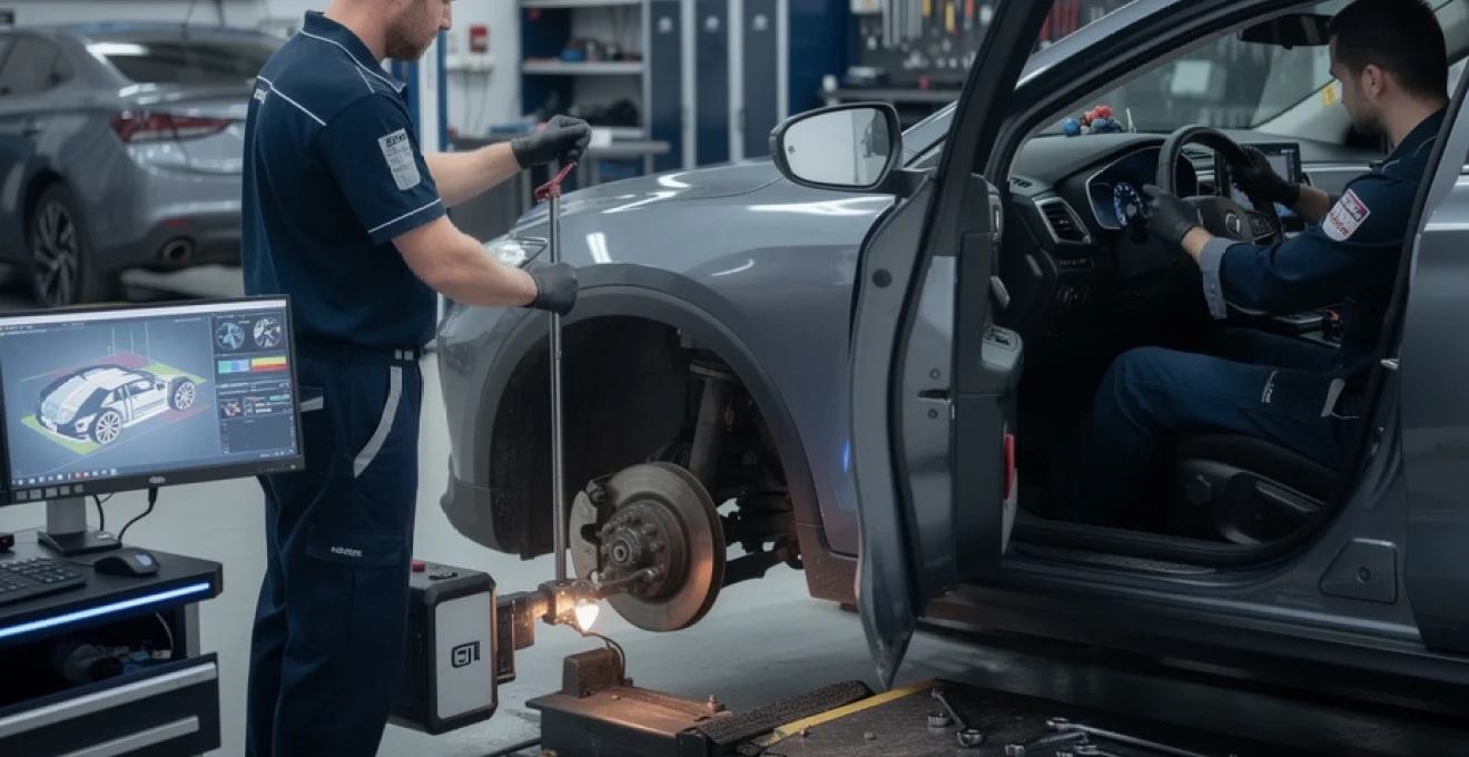
Diagnostic procedures using hunter engineering and john bean alignment systems
Modern alignment systems such as those from Hunter Engineering and John Bean provide far more than simple toe, camber, and caster readings. When used properly, these platforms can help pinpoint why a steering wheel is still not straight after alignment by revealing subtle geometric inconsistencies across the chassis. The key is not just to look at the green or red indicator bars, but to interpret the underlying data in the context of steering behaviour and vehicle dynamics. With a methodical approach to measurements like toe-out on turns, steering axis inclination, and caster split, you can distinguish between normal manufacturing tolerances and conditions that genuinely cause off-centre steering.
Interpreting toe-out on turns angles for ackermann geometry verification
Toe-out on turns measurements verify whether the inner and outer wheels follow correct paths when the steering is turned, a concept known as Ackermann geometry. On a Hunter or John Bean system, these readings are obtained by turning the steering to specified angles and observing the resulting toe changes. Significant deviations from the manufacturer’s toe-out on turns specifications can indicate bent steering arms, incorrect rack positioning, or modified components, any of which may contribute to a steering wheel not straight after alignment. Think of Ackermann geometry as the choreography of your front wheels in a turn; if one wheel is forced to “dance” out of step, the entire steering system compensates, often by shifting the neutral steering wheel position. When these readings are abnormal, geometric or structural faults must be corrected before fine-tuning toe for perfect steering wheel centralisation.
Analysing individual toe readings versus total toe specifications
Alignment printouts from Hunter and John Bean machines prominently display total toe for each axle, but the individual toe values for left and right wheels carry at least as much diagnostic weight. A car may show total toe exactly at the midpoint of the specified range, yet still produce a steering wheel off-centre if one wheel contributes most of that toe. For example, a total toe of +0.20 degrees could be split as +0.02 on the left and +0.18 on the right, effectively pulling the rack off-centre relative to the steering wheel. By comparing these individual readings and aiming for a near-symmetrical distribution, you create a strong foundation for straight-ahead steering without constant correction from the driver.
Cross-referencing steering axis inclination and included angle measurements
Steering axis inclination (SAI), combined with camber, forms the included angle—an important diagnostic value that reveals bent or displaced suspension components. Hunter and John Bean systems calculate SAI by comparing the change in camber as the wheel is steered through a known angle. If SAI or included angle differs significantly from side to side, it suggests that something in the knuckle, strut, or control arm geometry is no longer in its designed position. This mismatch can force the vehicle to develop a preferred steering direction, much like a misaligned rudder on a boat, and require you to hold the wheel at an angle to compensate. Cross-referencing these measurements helps distinguish between simple alignment drift and hard part damage that must be addressed before any lasting steering wheel centralisation is possible.
Validating caster split measurements against manufacturer tolerances
Caster describes the fore-aft tilt of the steering pivot and plays a major role in straight-line stability and steering wheel returnability. A small caster split, where one side has slightly more caster than the other, is sometimes used intentionally by manufacturers to counteract road crown. However, when caster split exceeds specified tolerances—say, more than 0.5 to 0.7 degrees difference—it can cause the vehicle to drift toward the side with less caster, forcing you to hold the wheel off-centre continually. Hunter and John Bean alignment equipment provide both numerical values and coloured tolerance bars, making it easy to see when caster asymmetry becomes problematic. Correcting this may involve shifting subframes, adjusting upper mounts, or replacing bent components to bring both sides back within the acceptable window.
Corrective adjustment techniques for steering wheel centralisation
Once diagnostic steps confirm that the core suspension geometry is sound, you can focus on the specific techniques used to bring the steering wheel back to true centre. Correcting a steering wheel not straight after alignment is not about guesswork or repeated test drives with random tweaks; it relies on controlled, symmetrical adjustments that respect the steering rack’s natural centre position. Depending on the vehicle’s design and the nature of the misalignment, you may use tie rod adjustments, steering wheel re-indexing, or direct steering rack repositioning to restore a precise straight-ahead orientation.
Equal-length tie rod adjustment method for symmetric toe correction
The equal-length tie rod adjustment method is the gold standard for ensuring that front toe corrections do not disturb steering rack centralisation. With the steering wheel mechanically locked at its perceived centre, you adjust each tie rod by identical amounts in opposite directions until individual and total toe readings meet specifications. For instance, if the steering wheel points slightly right while total toe is correct, you can shorten the right tie rod and lengthen the left by equal turns, shifting the rack relative to the wheels without altering total toe. This approach not only recentres the steering wheel but also maintains balanced steering response from lock to lock. Careful counting of flats or turns on each adjuster, supported by precise readings from the alignment machine, is essential to avoid reintroducing asymmetry.
Steering wheel removal and spline re-indexing procedures
In some situations—particularly when the underlying alignment and rack position are known to be correct—the steering wheel itself may have been installed off by one or more splines. This is more common after steering wheel or airbag replacement, or following steering column repairs. Correcting the issue requires safely removing the steering wheel and re-indexing it on the column splines so that the wheel appears level when the steering rack is at true centre. On modern vehicles equipped with airbags and steering angle sensors, this process must follow strict safety protocols, including battery disconnection, waiting periods to discharge capacitors, and proper torque application on the retaining nut. Once the wheel is reinstalled, the steering angle sensor often needs recalibration so electronic stability systems recognise the new straight-ahead reference point.
Addressing steering rack position using lock-to-lock counting method
When there is doubt about whether the rack itself is centralised, the lock-to-lock counting method offers a straightforward mechanical verification. You first turn the steering fully to one lock and note the position, then turn to the opposite lock while counting the exact number of turns (and fractions) of the steering wheel. Dividing this total by two gives the rack’s theoretical centre position, which you then set by rotating the wheel back accordingly and locking it in place. If, at this point, the steering wheel spokes appear visibly off-level, you know that either the wheel has been mis-splined or previous toe adjustments have pulled the rack off this true centre. Subsequent tie rod adjustments can then be made symmetrically from this verified midpoint, dramatically increasing the chances that the steering wheel will sit perfectly straight after the next road test.
Post-correction verification and road test protocols
No alignment or steering correction is complete until it has been validated in real-world driving conditions and documented with a comprehensive printout. The final steps focus on confirming that the steering wheel remains straight on typical roads, that advanced driver assistance systems understand the new steering reference, and that all measured angles fall comfortably within specification. Skipping this verification stage is a common reason why drivers find their steering wheel not straight after alignment, even when the workshop insists that “the machine says it’s fine.”
Straight-line tracking assessment on level road surfaces
The road test should begin on a level, low-traffic road where you can safely observe the vehicle’s natural tracking tendency. With the steering wheel held lightly at its apparent centre, the car should maintain a straight path without drifting more than a gentle lane width over several hundred metres. If you must hold the wheel noticeably to one side to avoid veering, further refinement of toe, thrust angle, or caster split is needed. It’s important to account for road crown by testing in both directions on the same stretch, asking yourself: does the steering wheel consistently sit straight when the car is genuinely going straight? Only when the vehicle tracks neutrally in both directions can you be confident that the centralisation work was successful.
Electronic stability control and lane keep assist system recalibration requirements
On many late-model vehicles, alignment and steering wheel centralisation are closely tied to electronic systems such as Electronic Stability Control (ESC), Lane Keep Assist (LKA), and adaptive cruise control. These systems rely on accurate steering angle sensor data to determine whether the vehicle is moving in the direction the steering wheel indicates. After correcting a steering wheel not straight after alignment—especially if you have re-indexed the wheel or altered the rack position—you may need to perform a steering angle sensor recalibration using manufacturer-specific diagnostic tools. Some lane-keeping and camera-based systems also require a dedicated calibration procedure on a level surface with alignment targets to ensure they interpret lane markings correctly. Ignoring these steps can lead to warning lights, unnecessary intervention from driver aids, or subtle pull and drift behaviours even when the mechanical alignment is perfect.
Documenting final alignment specifications using printout analysis
The final alignment printout is more than a receipt; it is a technical snapshot of your vehicle’s suspension geometry at the time of service. A thorough analysis should confirm that total and individual toe, camber, caster, thrust angle, and, where applicable, SAI and included angle, all fall within the manufacturer’s specified ranges. For long-term reference, retaining both the “before” and “after” readings allows you to track how the chassis responds to future impacts, modifications, or component wear. When you review the printout, check that left and right values are reasonably balanced and that thrust angle is close to zero—both are key indicators that the steering wheel should remain straight in everyday driving. With this documentation in hand, you have clear evidence that the alignment was completed to a professional standard and a solid baseline for any future diagnostics.